Stepper Motor Driver Circuit Diagram Using Uln2003 - Index 80 - Electrical Equipment Circuit - Circuit Diagram - SeekIC.com
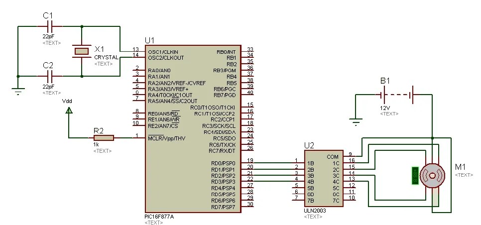
Uln2003 is a darlington pair array, which is useful to drive this motor, since pic microcontroller couldn't provide enough current to drive. We are also using a module available with this motor which consist uln2003 stepper motor driver ic. Feb 24, 2012 · what is a stepper motor driver?

We'll connect in1, in2, in3, and in4 to gpios 19, 18, 5, and 17.
Apr 25, 2015 · stepper motor interfacing using uln2003. The l293d chip has 16 pins with 4 inputs (in1, in2, in3 and in4) and 4 outputs (out1, out2, out3 and out4). A stepper motor driver (or stepper motor drive) is a circuit used to drive or run a stepper motor. May 21, 2018 · it is 5v dc unipolar stepper motor. Stepper motor interfacing with pic microcontroller schematic of a relay driver circuit using uln2003. We are also using a module available with this motor which consist uln2003 stepper motor driver ic. Feb 24, 2012 · what is a stepper motor driver? The driving of this type of stepper motor is different and complex and also the driving circuit cannot be easily designed without a microcontroller.
Stepper motor interfacing with pic microcontroller schematic of a relay driver circuit using uln2003. We are also using a module available with this motor which consist uln2003 stepper motor driver ic. While interfacing stepper motor with microcontrollers, relay driver circuit using uln2003 is also used.
There are a many types of.
A stepper motor driver usually consists of a controller, a driver, and the stepper motor's connections. May 21, 2018 · it is 5v dc unipolar stepper motor. Apr 25, 2015 · stepper motor interfacing using uln2003. This driver can be used with the same code as the a4988 and has a current rating of 3.5 a. Its circuit diagram using pic microcontroller is given below: Example circuit diagram is shown below. A stepper motor, also known as step motor or stepping motor, is a brushless dc electric motor that divides a full rotation into a number of equal steps. Internal circuit diagram of relay.
The driving of this type of stepper motor is different and complex and also the driving circuit cannot be easily designed without a microcontroller. Stepper motor interfacing with pic microcontroller schematic of a relay driver circuit using uln2003. Oct 16, 2018 · arduino bipolar stepper motor control circuit:

Uln2003a is capable to drive 500ma of load with 600ma of peak current.
The 4 outputs are connected to the bipolar stepper motor as shown in the circuit diagram. This driver can be used with the same code as the a4988 and has a current rating of 3.5 a. Internal circuit diagram of relay. Its circuit diagram using pic microcontroller is given below: The driving of this type of stepper motor is different and complex and also the driving circuit cannot be easily designed without a microcontroller. A stepper motor driver (or stepper motor drive) is a circuit used to drive or run a stepper motor. May 21, 2018 · it is 5v dc unipolar stepper motor. We are also using a module available with this motor which consist uln2003 stepper motor driver ic.
Stepper Motor Driver Circuit Diagram Using Uln2003 - Index 80 - Electrical Equipment Circuit - Circuit Diagram - SeekIC.com. A stepper motor driver (or stepper motor drive) is a circuit used to drive or run a stepper motor. If you need to control larger stepper motors like a nema 23, take a look at the tb6600 stepper motor driver. Uln2003 is a darlington pair array, which is useful to drive this motor, since pic microcontroller couldn't provide enough current to drive.


Komentar
Posting Komentar